.png?width=400&height=400&ext=.png)
Can we see inside soil? X-ray CT scans open up a new view of geomechanics
Date: August 25, 2026
One of the frustrations in geotechnical engineering is that the most important things are often happening where we cannot see them. Soil and aggregate may look simple enough from the outside, but the real behaviour is hidden within the material: particles moving, rotating, interlocking, and transferring load in ways that control strength, stiffness and long-term performance. That is exactly why X-ray computed tomography (X-ray CT) is such an exciting development for soil mechanics and geomechanics. It allows us to look inside a specimen non-destructively and build a true three-dimensional picture of what is happening within it.
In this episode of Tensar Ground Coffee, filmed at Université Grenoble Alpes, I had the chance to demonstrate the technique using the actual X-ray CT apparatus at the university’s renowned 3SR laboratory. Grenoble has been one of the pioneering centres in applying X-ray tomography to geomechanics, with a dedicated tomography platform and a long track record of combining advanced imaging with experimental soil mechanics.
So, how does X-ray CT work?
The basic principle is familiar from medical imaging. An X-ray source emits radiation through the object being tested, and a detector records how much of that radiation is attenuated as it passes through. Dense materials attenuate the beam more strongly than air-filled voids, so particles show up differently from the surrounding space. In the Grenoble setup shown in the video, the specimen is placed on a rotating stage and scanned through many angular positions so the system can reconstruct a 3D image from a large number of 2D radiographs.
That is the key difference between a single X-ray and a CT scan. A single radiograph gives just one projection. A CT scan acquires many projections all the way around the specimen and reconstructs them into a volumetric image. In the geomechanics application demonstrated in Grenoble, this means we can generate vertical sections, horizontal slices, or a full 3D model of the entire aggregate column. More importantly, if we scan before and after loading, we can compare the images to determine how the particles have moved and rotated.
Why is that useful in geomechanics?
Because geomaterials are opaque and highly heterogeneous. Traditional laboratory tests can tell us the overall response of a specimen — stress, strain, stiffness, or strength — but not usually the internal mechanisms that produced it. X-ray CT helps bridge that gap. It is non-destructive, it captures the internal structure in three dimensions, and when paired with image analysis tools such as digital volume correlation (DVC), it can quantify internal kinematics throughout the specimen. That has made it a valuable research tool for studying localisation, cracking, root–soil interaction, freezing effects, and granular behaviour in soils and rocks.
For geotechnical engineers, that is a big step forward. We are no longer limited to inferring mechanisms indirectly from surface observations or post-test excavation. We can now see where deformation concentrates, how it evolves, and how inclusions such as fibres, roots, or geogrids influence the response of the surrounding particles. SmartRocks, which are artificial stones with accelerometers inside to detect movement, provide continuous particle movement data at their specific locations. The advantage of X-ray CT is that the rocks are real and we can see every one – it’s as though every rock is a SmartRock!
Seeing mechanical stabilisation inside aggregate
That is where this becomes especially relevant to Tensar. We know that geogrids stabilise aggregate by creating interlock and confinement. Aggregate particles penetrate into the apertures, their movement and rotation are restricted, and this changes how load is distributed through the granular layer. That stabilisation effect is well established at the macro scale through performance testing and field behaviour. What has been much harder to observe directly is the particle-scale mechanism inside the aggregate mass.
Recent work by Belachew et al. used X-ray CT at Université Grenoble Alpes to do exactly that on aggregate columns containing Tensar InterAx geogrid. Two cylindrical specimens were tested under uniaxial compression: one non-stabilised and one containing two geogrid layers. CT scans were taken before and after loading, and DVC was then used to determine the motion of individual particles. The results gave a remarkably clear picture of how the geogrid changed the internal behaviour of the aggregate.
The non-stabilised specimen showed larger particle displacements and rotations distributed through much of its height. By contrast, the geogrid-stabilised specimen exhibited a more layered response, with reduced magnitudes of displacement and rotation and clear stratification associated with the positions of the embedded geogrid layers. In simple terms, the geogrid was not just affecting the particles touching it directly; the restraint was being transferred through inter-particle contact into a wider zone of the aggregate creating a mechanically stabilised layer (MSL).
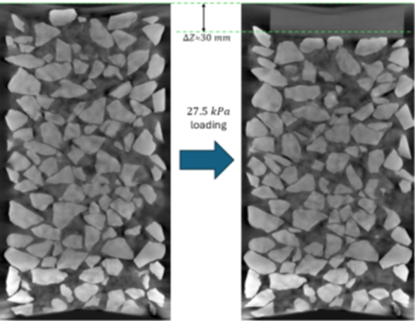
The quantitative reductions were significant. Compared with the non-stabilised specimen, the geogrid-stabilised specimen showed an approximately 82% reduction in mean particle displacement and a 73% reduction in mean particle rotation. Maximum displacement and rotation were also substantially lower. Those results provide compelling micromechanical evidence of the confinement and stabilisation effect that geogrids are intended to deliver.
Why this matters for design
This kind of imaging does more than produce impressive pictures. It improves understanding. If we can observe how aggregate particles actually behave around a geogrid under load, we can build better physical explanations, better numerical models and, ultimately, better design methods. That means more confidence in the stabilisation mechanism, better optimisation of geogrid geometry and stiffness, and better value for designers and asset owners.
It also reinforces an important point that Tensar has long made: geogrid performance should not be judged simply by isolated index properties, but by how effectively the product interacts with the surrounding aggregate to improve the behaviour of the whole stabilised layer. X-ray CT provides an unusually direct way of seeing that interaction.
A powerful research tool — with practical relevance
Of course, X-ray CT is not going to replace conventional geotechnical testing for day-to-day design. It is a specialist research technique requiring sophisticated equipment, careful specimen preparation and extensive image processing. But as a tool for uncovering hidden mechanisms, it is hugely valuable. It helps answer the sort of questions geotechnical engineers have always wanted to ask: where does deformation start, how does it spread, and what exactly is the geogrid doing inside the aggregate?
And perhaps that is the real attraction of the technique. For years we have described mechanical stabilisation in terms of interlock, confinement and restricted particle movement. Now, increasingly, we can actually see it.