.jpg?width=400&height=400&ext=.jpg)
Bridge Abutments: Types, Designs & Construction
Date: August 28, 2025
Bridge abutments are the supportive structures positioned at either end of a bridge. Abutments form part of a bridge’s substructure, providing support for its superstructure (which is the main deck of a bridge that lies above its support system). Their role is to elevate the superstructure and connect it to the underlying foundation. They may also function as a retaining wall system for the ends of the bridge approach embankments.
To provide this support, an abutment must be built to withstand multiple vertical and lateral forces throughout its design life: civil engineers must account for loading from the weight of the bridge deck and any traffic using the bridge, thermal expansion forces from the deck, earth pressure from the embankment fill, vehicle breaking, and from external sources such as wind, ground water pressure, water flow, and earthquakes.
Some bridge abutment structures are designed to carry both vertical and horizontal loads and transfer these to the foundation. In others, the vertical deck loads may be carried by one structure and horizontal loads carried by a separate structure, such as a Tensar reinforced soil wall. The types of abutment and design options for each type are covered in greater depth below.
 A bridge design where all deck loads are transferred onto reinforced soil abutments.
You may already have gathered that there are many different types of bridge abutments in use. Over the course of this guide, we’ll take a closer look at these as well as exploring important facets of bridge abutment design and construction. To put all of this into practice, we’ve included three real-world bridge abutment case studies from Tensar at the end.
Looking for something in particular? Use the links below to navigate straight to it:
Tensar is a leading global provider of bridge abutment solutions using geogrid retaining walls
Discover more about how these systems reduce project costs and timelines compared to the alternatives.
Get in touch for a free consultation
Where are bridge abutments used in civil engineering?
No bridge can be constructed without suitable abutments to support it. Civil engineers use abutments to support bridges in highway design, elevated structures for railways, as well as crossings over waterways.
The most visible bridge abutments are associated with elevated bridges, where the abutments support the bridge deck, and also create a steep or vertical end face to the approach embankments, preventing encroachment beneath the bridge span.
Where bridge decks are at or near ground level, such as for narrow waterway crossings or subways, the abutments support the deck loads and retain the earth vertically at each end of the bridge to create maximum channel width.
Wherever you see a bridge that crosses a river, the abutments must also incorporate erosion protection to the foundation. Addition scour protection (such as riprap) can also be added at the base of the abutment to prevent undercutting from the action of water.
The components of a bridge abutment
There is significant variation between the designs used for bridge abutments – but most will feature certain key components constructed from concrete or masonry. Not all of these will be incorporated into every abutment type. Take a look at the diagrams below, then read on to find out more about each of these parts and the roles they play within the overall structure.
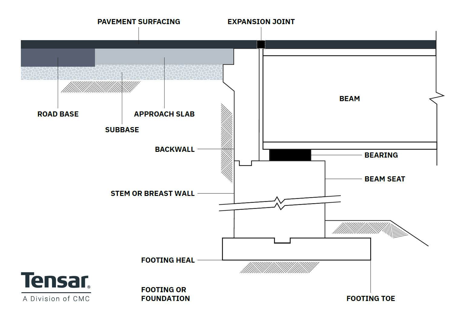 Figure 1- The common components of a bridge abutment.
Abutment foundation or footing
Forming the base of the abutment, the footing or foundation supports the overall structure and transfers vertical and lateral loads from the bridge and lateral loads from the retained embankment fill to the ground. It must also distribute these loads effectively to reduce stress on the ground, which could otherwise lead to excessive settlement.
There are two most common types of bridge abutment foundation to be aware of:
- Piled foundation – used in cases where the underlying soil is weak, The footing sits on a group of steel or concrete piles that are driven into the ground. In some cases, reinforced concrete piles may be cast-in-place within deep boreholes.
- Spread footings – as the name suggests, these spread load over a wide area but are only suitable if the underlying soil is strong enough without the need for a piled foundation. In some cases, weak soils may be excavated to expose stronger soils or bedrock rock on which to construct the spread footing.
Back wall
These vertical concrete walls at the end of the bridge deck support the approach slab (the part of the bridge deck that connects to the embankment). They also contain the embankment soil behind an abutment. In this way, back walls supports the upper bridge approach earthworks, stopping soil from encroaching into the bridge span.
Wing Wall
Primarily intended to retain the approach embankment (the section of soil or fill leading up to the bridge), these walls are built outwards from the bridge abutment. Designs vary: often wing walls extend outward in-line with the abutment wall, some angle back towards the embankment, whilst others wrap around 90° to the abutment face creating vertical sides to the approach embankment. The latter design is used when you’re looking to minimise the embankment footprint to maximise usable space.
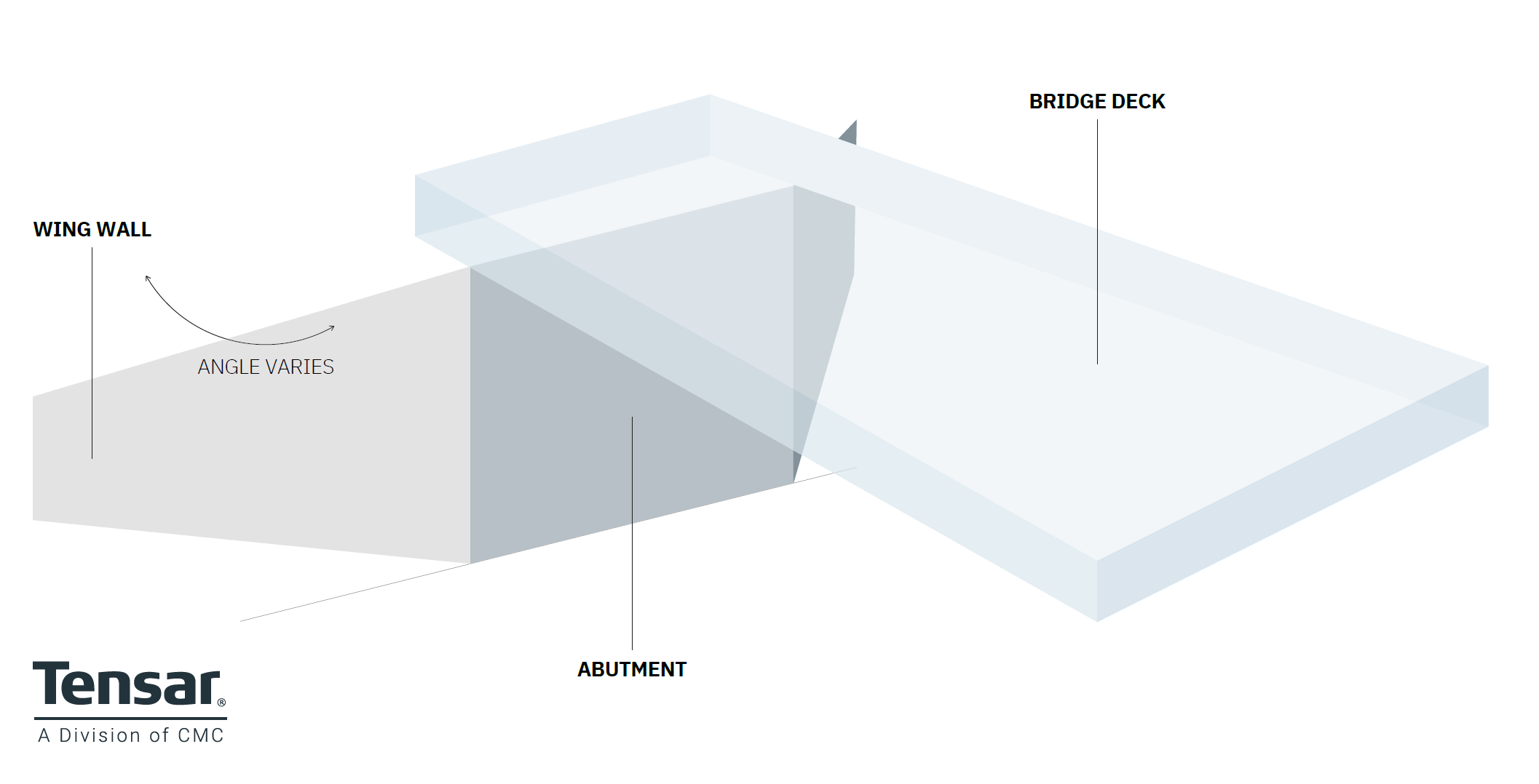
Figure 2 - The wing walls extend from the abutment to retain the approach embankment fill.
Bridge seat or beam seat
This acts as a platform for the main bridge deck, making up the top portion of a bridge abutment. The main function of the bridge seat is to support the load from the bridge and distribute it evenly to the substructure and then to the ground.
Approach slab
The approach slab provides a smooth transition from the bridge deck to the approach embankment. It is designed to reduce local settlement within the backfill and accommodate the likely differential settlement between the bridge structure and approach embankment caused by consolidation of the foundation soil below the embankment. The smoothing transition zone can be extended beyond the approach slab by mechanically stabilising the subbase layer below the slab and some distance along the top of the embankment. This is important for highway structures, but is of particular value for railway structures, where differential settlement effects track speed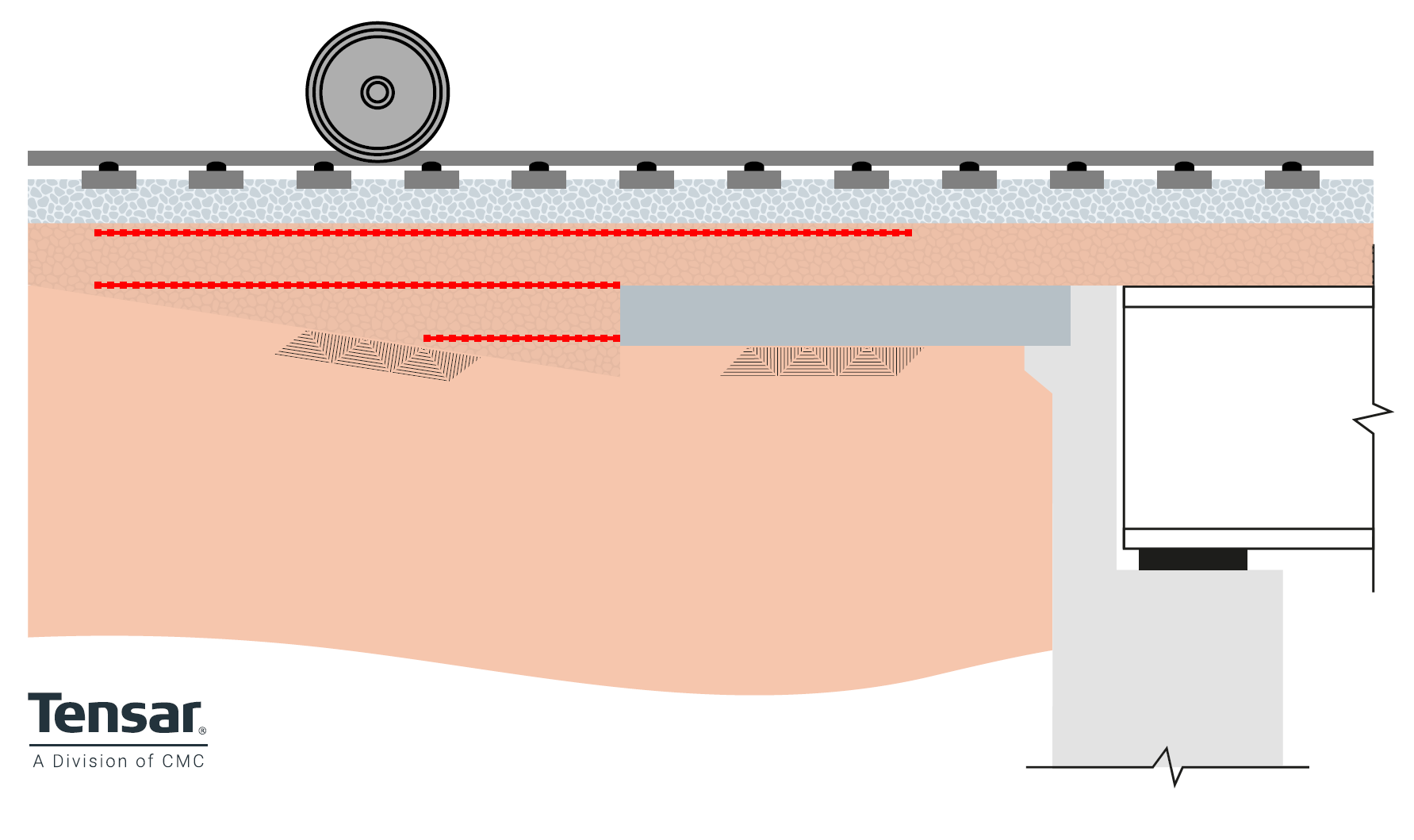
Figure 3 - Mechanical stabilisation of the transition zone beyond the approach slab to reduce differential settlement adjacent to abutments.
Bridge bearing
The loads from the bridge superstructure are transferred to the substructure through bearings. These are located between the deck beams and the beam seat or bank seat. The design of these bearing can be complex. Bearings divide into two types; those that allow rotational movement (flexing of the superstructure), transferring vertical and lateral forces to the bank seat, and those that allow both rotational and lateral movement to take place, transferring only vertical load to the bank seat. In some instances, the bridge superstructure connects directly to the substructure without a bearing, these are called integral bridge structures, and we cover these in more detail below.
Expansion joint
Movement of the bridge superstructure can be accommodated by expansion joints that separate the bridge deck from the approach structure. Lateral movements can arise from expansion and contraction of the superstructure due to temperature changes, both daily and seasonally, from creep and shrinkage of the deck materials, and from settlement of the abutments, particularly in areas susceptible to mining subsidence. Expansion joints require regular maintenance, and at some point in time, will require replacement, which can be expensive and highly disruptive to users. As a result, integral bridge structures, without expansion joints, are now the first choice for many road authorities. This is now a requirement in the UK as specified in the Design Manual for Roads and Bridgeworks CD350, Section 8 -Design for Durability . More on these below.
.jpg)
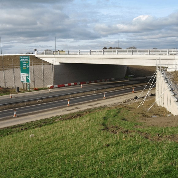
Figure 4 - A bridge abutment under construction as part of the M42 Junction 6 improvement project.
Types of bridge abutments
Engineers looking to choose the right sort of bridge abutment for an upcoming project need to consider a range of factors that will include cost constraints, the required length, height and skew of the bridge deck, as well as soil conditions below the abutment. There are two basic structural forms, gravity structures and embedded structures. With gravity structures, the overturning forces and sliding are resisted by the mass of the structure, while embedded structures rely on the below ground passive earth pressure to resist overturning and sliding. Have a quick scan of the design descriptions and use cases below to review the abutment options available.
Embedded abutment
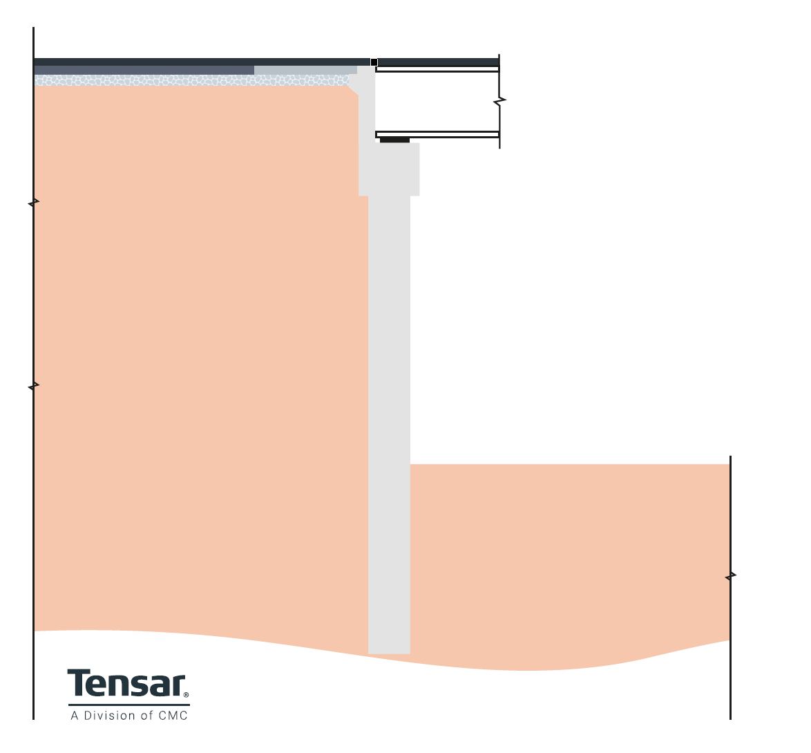
Figure 5 Embedded abutment.
Design – The abutment wall extends deep into the foundation soil. Overturning forces are resisted by the passive earth pressure of the foundation soil. Concrete or driven steel piles can be used to form the wall.
Use cases – Best suited for medium height structures. Can be economical and relatively quick to construct where ground conditions are suitable. Particularly cost effective where ground conditions would require piled foundations for gravity structures.
Cantilever wall abutments
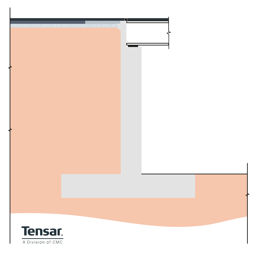
Figure 6 - Cantilever abutment.
Design – a cantilever retaining wall is used (with a base slab and stem offering resistance to both bridge loads and earth pressures). Overturning can be a risk: to avoid this, the wall stem must be analysed for bending and shear, and the base slab usually needs to have a deep foundation to withstand bearing pressures.
Use cases – we typically use a cantilevered abutment where the approach embankment is relatively high, and in cases where there’s a concern about differential settlement. The ability to have a thinner section of wall can decrease concrete volume requirements compared to the likes of gravity abutments, bringing cost and carbon reduction benefits.
Bank pad or Stub abutments
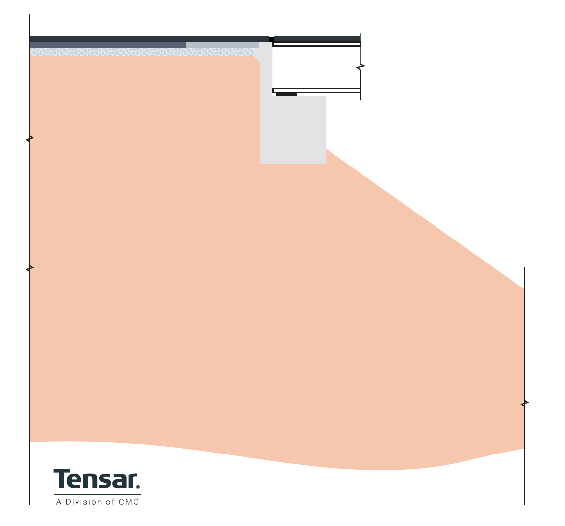
Figure 7 Bank Pad or Stub abutments.
Design – a short back wall, often supported by independent wing walls that will retain the approach embankment. Can use either spread or piled footings, with the latter favoured if the underlying soil is weaker.
Use cases – this type of abutment is relatively inexpensive in itself, but separate wing wall requirements can increase the costs. Only suitable for shorter spans where the approach embankment is not too high.
Semi-stub abutments
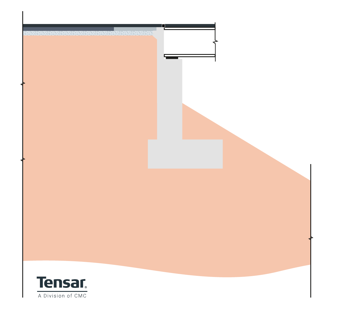 Figure 8 - Semi-stub abutment
Design – modifying the standard stub abutment design by having a higher wall to help retain the approach embankment to a greater extent.
Use cases – like stub abutments, the semi-stub design should only be considered if the approach embankment isn’t excessively high; however, semi-stub abutments can withstand more lateral earth pressure than their shorter counterparts whilst still bearing the bridge load, allowing for an increase in the height of the approach embankment by comparison.
Counterfort abutments
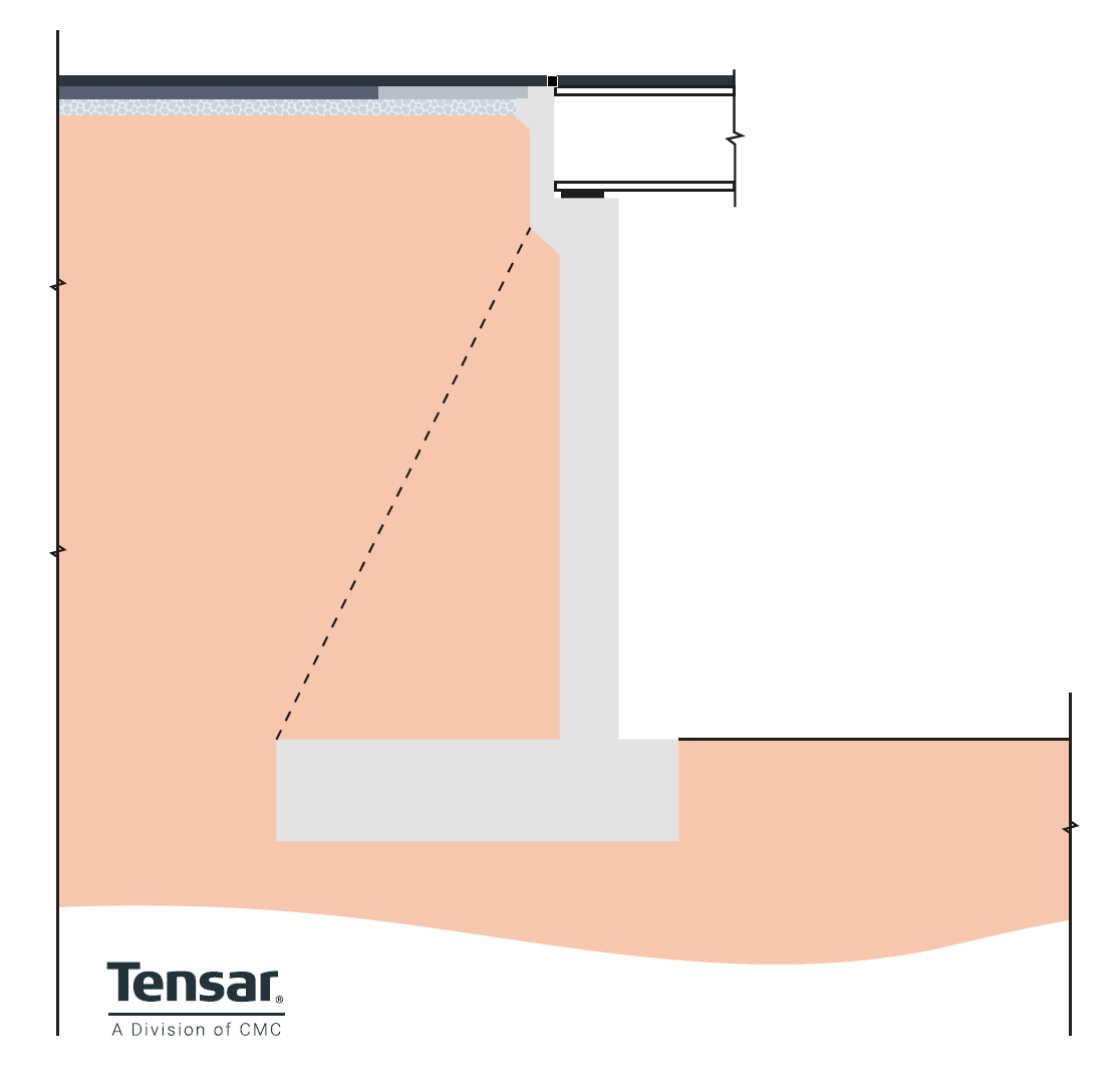
Figure 9 - Counterfort abutment.
Design – building on the design of a full-height abutment by introducing counterforts (triangular buttressing structures) to the back wall on the earth side. The required thickness of the wall can be reduced in this way, as the counterforts give us extra resistance to bending.
Use cases – ideal if we need to construct a bridge with very tall approach embankments. The design process for counterfort abutments may be more complicated than other types, but you can reduce material costs by having a thinner back wall.
Gravity Abutments
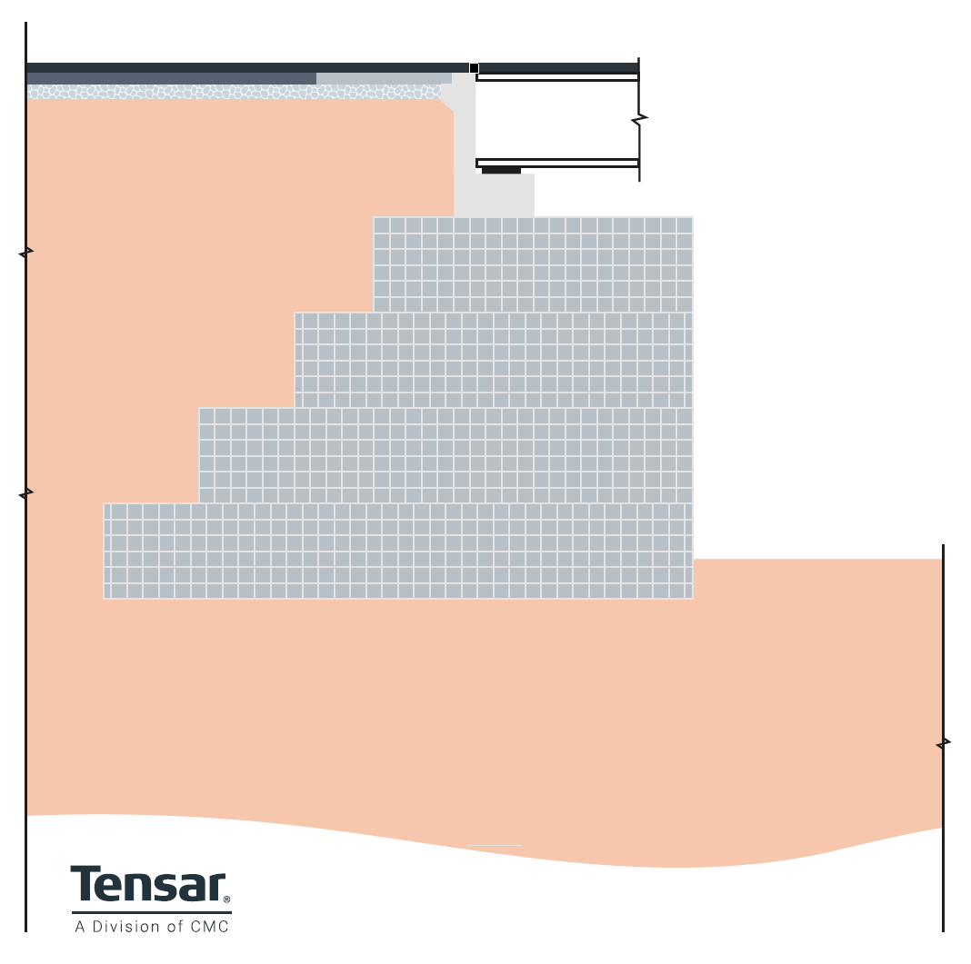
Figure 10 - Gravity abutments.
Design – following the same principles as gravity retaining walls, these abutments rely on their mass to resist the sliding and overturning forces from the lateral earth pressure imparted by the embankment soil behind them. They can be constructed from mass concrete, but this is expensive. For smaller structures gabions or large concrete blocks may be used.
Use cases – shorter span low-level bridges where the underlying soil offers a strong enough foundation for a wide, stable base.
Spill-through abutments
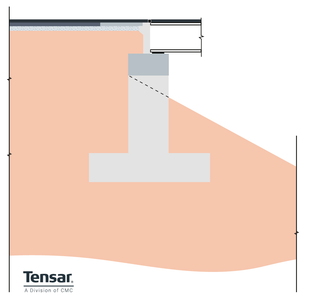
Figure 11 – Spill-through embankments.
Design – Spill-through abutments allow the earth or rock that makes up the approach embankment to “spill through” openings situated underneath the bridge deck. They’re sometimes called pedestal abutments, as the design typically consists of short stub walls supported on pedestals or columns.
Use cases – most often used when building a bridge that crosses a wide valley, and the approach embankment can be stabilised effectively. In such cases, spill-through abutments can reduce substructure costs. They can also be used where there is an intention to add an additional span in future. In that case the spill-through abutment becomes a central pier.
Reinforced soil or mechanically stabilised earth abutments
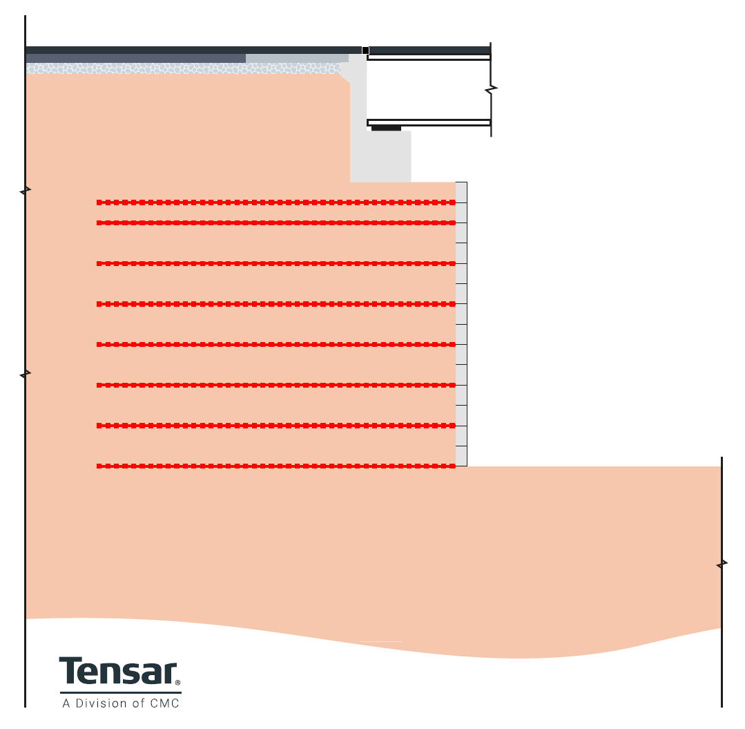 Figure 12 - Reinforced Soil or Mechanically Stabilised Earth abutment – Load bearing.
 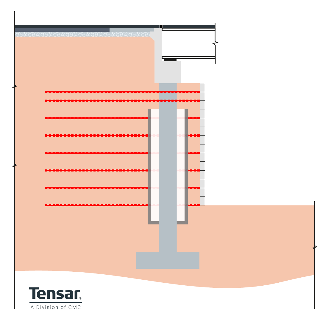 Figure 13 - Reinforced Soil or Mechanically Stabilised Earth abutment – Non-load bearing
Design – A specific form of abutment, where the stabilising structure is formed from reinforced soil. The structure comprises a zone of soil reinforced with geogrids or other reinforcing elements. Also referred to as a mechanically stabilised earth (MSE) structure. A non-structural facing of modular concrete blocks or segmental concrete panels provides an architectural finish. The facing units are connected to reinforced soil structure using high-strength connectors to form a solid abutment structure with a long design life. The reinforced soil structure can be designed to carry the full superstructure loads (load bearing) or may carry only lateral earth pressure from the embankment fill with the superstructure loads transferred to the ground by piles of columns (non-load bearing). Tensar has several reinforced soil systems suitable for bridge abutments for load bearing and non-load bearing structures. Tensar structures are also suitable for fully integral bridge abutments – more on these later.
Use cases – if your project demands flexibility, rapid construction, and low costs, reinforced soil abutments are an ideal choice. They’re also well-suited to scenarios where the foundation soil is weak.
Design considerations for bridge abutments
There are many factors that will influence the choice of bridge abutment for a specific project. While safety and durability concerns may top the list, engineers will need to consider the available budget, the live loading and design life required, the topology and geotechnical conditions, the availability of construction materials and fill types, groundwater and surface water flow, plus the aesthetic and environments requirements.
Loading of bridge abutments
The design must consider the combination of dead load and live loading. Live loading on the superstructure needs to include breaking forces, thermal expansion and shrinkage forces, wind load, and seismic loads. The type of abutment will determine how these forces are transferred through the abutment to the ground.
Design life of bridge abutments
For the majority of highway and rail structures, the design life for bridge works is defined by the client authority. In the UK this is usually 120 years for road projects. However, the bridge may have a shorter design life requirement, for example a quarry access road crossing or a temporary bridge for construction work. The design life could influence the choice of materials used and may affect aesthetic requirements.
Geotechnical considerations for abutments
The geotechnical conditions will have a major influence on the choice of abutment type. Particularly whether a piled or spread footing is appropriate and the depth of foundation required. The design will also be influenced by the predicted relative settlement of the approach embankment and abutment structures. The presence of mine workings will dictate the design of bearings and support structures.
Topology influences on abutment selection
The gradient of the ground at the abutment site and approach embankment will impact on the abutment type selection. On steeply sloping valley sides, full height abutment walls will be expensive, favouring bank seats on piles or spread footings. Space constraints or steeply sloping ground may also favour retaining walls or steep reinforced soil slopes to reduce the width of approach embankments.
Groundwater and surface flow influences on abutments
As with all structures in contact with the ground, the effects of groundwater movement and pressure must be accounted for in the design. Hydrostatic pressure behind the abutment wall can be reduced or eliminated by correctly designed drainage incorporated into the structure. Flowing water across the face of the abutment, whether continuous river flow, or intermittent stormwater flow, requires the design of erosion protection measures.
Aesthetic considerations and architectural finishes for abutments
The location and required design life will in most cases determine the importance of aesthetics for bridge abutment construction. In most cases, bridge works and the associated abutments are highly visible long-term structures and aesthetics are important. Architectural input into the design process will ensure that the structure is attractive and compatible with its surroundings. Tensar reinforced soil systems for retaining walls and bridge abutments are available in a range of durable architectural finishes and colours.
Environmental impact
Concrete is the least eco-friendly material for constructing bridge abutments, but as we’ve seen it is often a necessary design choice. If you are prioritising sustainability as part of your project, consider opting for a design that minimises the quantity of concrete used: Tensar reinforced soil bridge abutments use a modular concrete block facing with geogrid reinforced soil behind, reducing overall carbon emissions by contrast to in-situ concrete systems.
Learn more about sustainable infrastructure solutions with geosynthetics.
Design more cost-effective bridge abutments with TensarSoil
Our TensarSoil software is free to use, simply request the software below.
Enquire about TensarSoil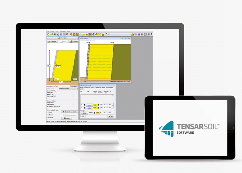
Integral bridge abutments
The expansion and contraction of bridge decks, due to thermal effects, creep, and shrinkage, causes lateral movements to occur. These have traditionally been accommodated by allowing the superstructure to slide laterally at one end or between spans. Movement joints in the deck and surfacing are installed to allow this movement. These require regular maintenance and occasional replacement. This is costly and highly disruptive users and operators. Failing, noisy bridge joints are a common source of complaint from road users. In response to this, bridge engineers across the globe have been increasingly adopting a joint free solution. Integral abutment bridges have no movement joints. The superstructure is connected directly to the substructure. This has a major impact on the design of the bridge abutments, which must now carry high expansion loads and accommodate the associate lateral movements into the approach embankments. Integral abutment bridges can be fully integral or semi-integral. The differences are explained below. Tensar has developed expertise in the use of reinforced soil structures for integral and semi-integral abutments. Many Tensar reinforced soil structures have been designed and constructed for integral and semi-integral abutment road bridges with 120 year design life.
Fully Integral bridge abutments
With fully integral abutment bridge structures, there are no movement joints in the deck. The superstructure is directly and rigidly connected to the abutments. No relative movement is possible, lateral or rotational. All lateral forces and rotational forces are transferred directly into the bridge abutment. Thermal expansion and contraction movements are accommodated by the abutment moving into and out of the backfill. In the UK, recommendations for design of integral bridge abutment are provided by PD6694-1, Recommendations for the design of structures subject to traffic loading to BS EN 1997-1. London, UK: BSi (British Standard International); 2011
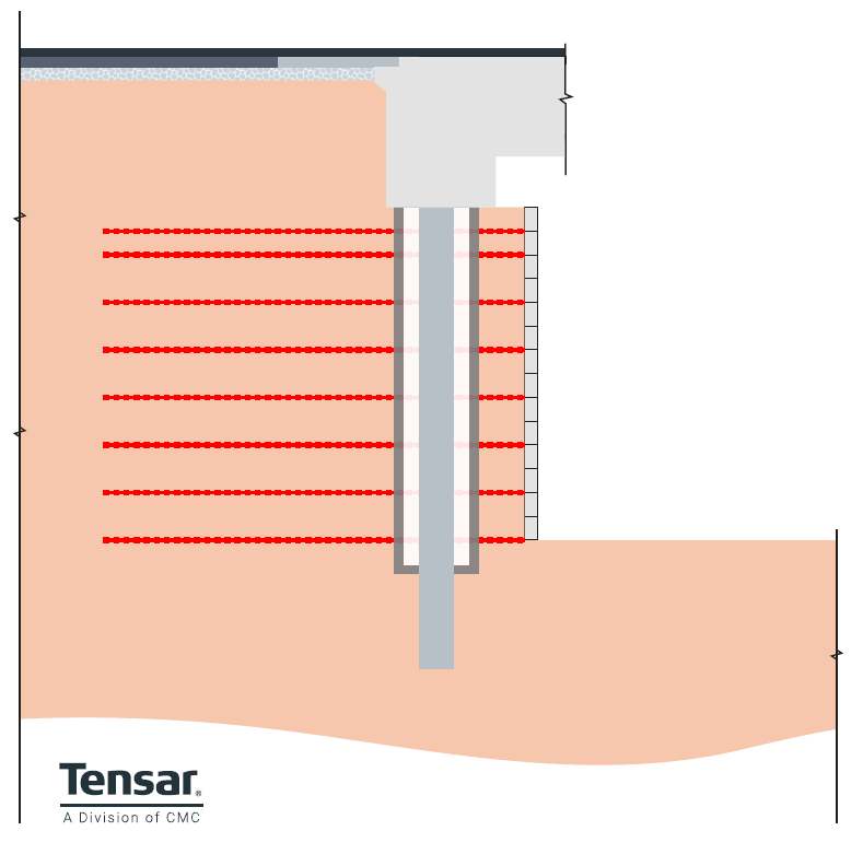
Figure 14 - Reinforced soil (Mechanically Stabilised Earth) Integral Abutment with tied columns – Type 1. Columns carry vertical and lateral superstructure loads. Columns are free to flex within casing, isolated from the reinforced soil structure.
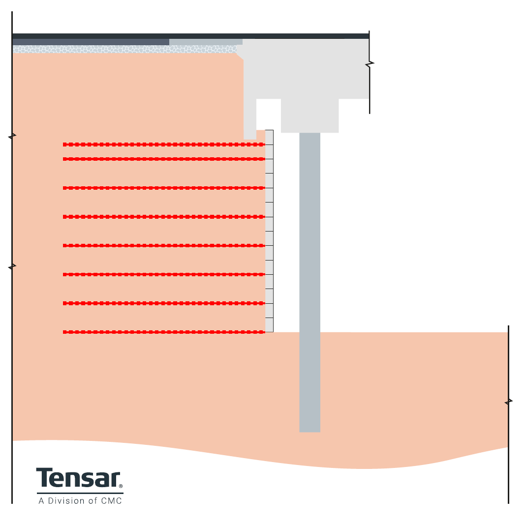
Figure 15- Reinforced soil (Mechanically Stabilised Earth) Integral Abutment - Type 2. Reinforced soil end screen wall carries earth pressure and lateral superstructure loads. Columns free to flex. 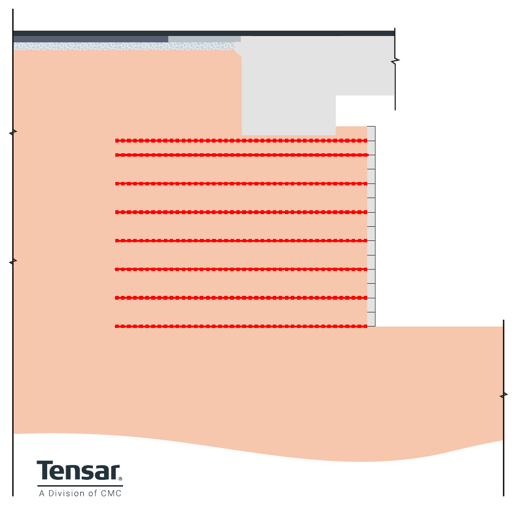
Figure 16 - Reinforced soil (Mechanically Stabilised Earth) Integral Abutment with bank seat - Type 3, all superstructure load is transferred through the bank seat to the reinforced soil structure.
Semi-integral bridge abutments
Semi-integral abutment bridge structures also have no movement joint in the deck. However, there are bearings between the superstructure and the abutment that allow for rotational and lateral movements. This removes lateral and rotational forces from the supporting structure. These forces are transferred through the back wall into the embankment, with expansion and contraction accommodated by movement of the backwall into and out of the backfill. 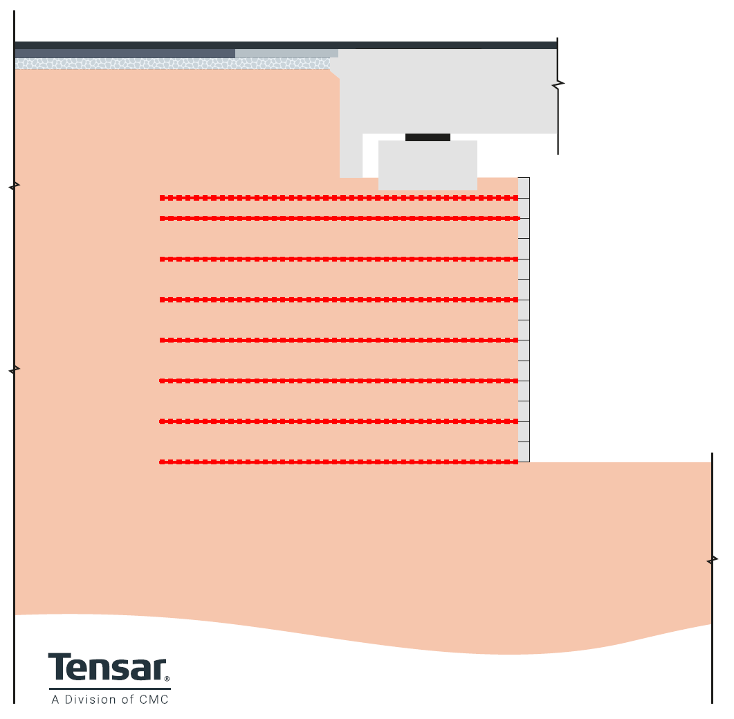
Figure 17 - Reinforced soil (Mechanically Stabilised Earth) Semi-integral Abutment – A bearing allows lateral movement between superstructure and bank seat; lateral is restraint provided by backfill pressure behind the back wall.
Advantages of reinforced soil bridge abutments
Reinforced soil abutments, also referred to as Mechanically Stabilised Earth (MSE) bridge abutments, utilise reinforcing or stabilising elements to create a strong and durable soil structure. The elements can be steel, or more commonly geosynthetics, typically geogrids. The reinforced soil abutment may carry only lateral earth pressure imparted from the embankment fill, referred to as a non-load bearing bridge abutment.- or the bridge superstructure loading can also be transferred directly onto the reinforced soil mass, referred to as a load bearing bridge abutment.- We’ve touched briefly on the sustainability benefits of this design approach already, but let’s unpack more of the reasons behind its increasing popularity.
Shorter construction timelines
When planning a bridge construction project, reducing disruption to surrounding roads, infrastructure, and communities is a top priority. And one of the best ways to achieve this is by shortening construction timelines.
Reinforced soil earth abutments can be constructed in as little as three days once excavation is completed. You don’t typically need deep foundations, as the full base area of the reinforced soil mass acts as a spread footing. On top of this, the ability to incorporate site-won materials into the design can reduces time, whilst also making projects more eco-friendly.
More cost-effective
With concrete bridge abutment designs, foundation preparation costs can mount up – particularly where extensive piling is required. Reinforced soil abutments reduce the amount of work that goes into preparing the foundation, generating substantial cost savings.
The use of reinforced soil integral bridge abutments eliminates the need for deck joints. This greatly reduces the costs and disruption associated with joint maintenance and replacement. Also, by eliminating abrupt differential settlements between the approach embankment and the abutment, the surface profile is maintained, eliminating potential surface reinstatement costs.
Environmental benefits of reinforced soil abutments
Concrete has a very high construction carbon cost. It requires significant quantities of energy to produce Portland cement, and to quarry, process and transport the high quality aggregates required for concrete production. Compared to concrete bridge abutments, reinforced soil abutments have a significantly lower construction carbon cost. The quantity of concrete required for the modular concrete block facing of reinforced soil structures is significantly less than for in-situ concrete structures. In many case, site-won or recycled material can be used for the backfill and structural fill of reinforced soil abutments. This has major benefits when seeking to reduce the construction carbon footprint on a project.
Temporary bridge abutments
There are many occasions where a bridge may be required for a short period. Examples would be a temporary crossing to allow repair or replacement of an existing bridge crossing, providing bridge access to a project quarry or borrow pit, or part of diversionary enabling works during a major construction project. In these cases, the design and construction method adopted for bridge abutments can take advantage of the short design life to minimise costs.
Reinforced soil bridge abutments can be designed and constructed using a low-cost facing system that provides full functionality for the required design life, but without the aesthetics and long-term durability of a permanent structure. The TensarTech TR2 wall system had been developed for temporary retaining structures and has been successfully adopted for multiple road and rail projects. 
Figure 18 - The TensarTech TR2 wall system is well suited for temporary bridge abutments, offering a low-cost solution.
Tensar Bridge abutment case studies
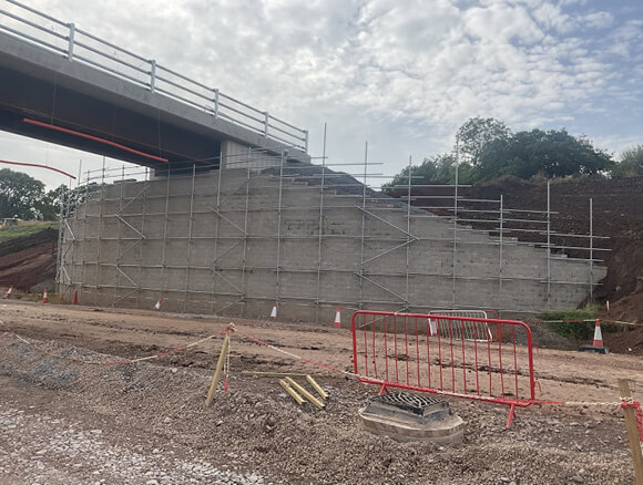
M42 Junction 6 – Semi integral abutment
As part of the re-modelling of the M42 Junction 6, a 60° skew overbridge was needed to cross a section of dual carriageway. The 83m long superstructure is supported on semi-integral abutments constructed using the TensarTech TW1 reinforced soil system. This system was chosen by the construction team for its simplicity of construction and lower carbon cost compared to the in-situ concrete alternative. See the full case study here. 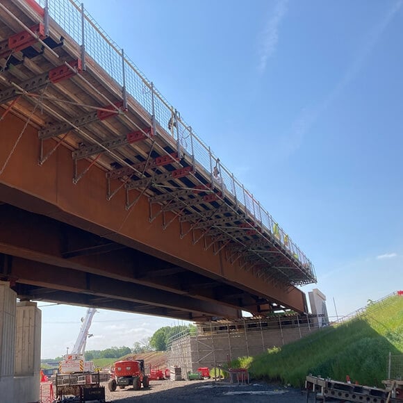
Figure 19 - TensarTech TW1 system used for the semi-integral bridge abutments.
A24 Broadbridge Heath – Integral abutment
On the A24 Broadbridge Heath project, the construction of a relief road linking two major housing schemes required building a new bridge over the A24 dual carriageway. The bridge had to be built quickly and safely, causing minimal impact on the main development works and without disrupting traffic.
Tensar’s TensarTech®TW3 Wall System was used to build the load-bearing bridge abutments and wing walls for the new bridge. This geogrid-reinforced soil structure and mechanically connected concrete block facing support the 28m span bridge deck. Construction of the modular concrete block retaining wall was fast and easy, reducing crane lifts and keeping A24 closures to a minimum. See the full case study here.
Tensar’s modular TW3 Wall System enabled the fast and low-impact construction of bridge abutments and wing walls for a new 28m span bridge over the A24 at Broadbridge Heath.
A14 Cambridge to Huntington – Temporary bridge abutments
The TensarTech TR2 reinforced soil system was used to construct three temporary bridge abutments on this major highway project. Temporary bridges were required to carry haul roads over a dual carriageway road during the 18-month construction period. The system uses a steel mesh facing for the reinforced soil structures. This provided a low cost, but effective solution. You can see a full case study here. 
Figure 20 - The TensarTech TR2 reinforced soil system provided the ideal low-cost solution for these temporary bridge abutments.
Design more cost-effective, durable bridge abutments with Tensar
This guide has introduced you to bridge abutments, the different types available, and the key design considerations to ensure stability and long-term performance. We’ve also looked at how reinforced soil structures can be used to enhance abutment designs – decreasing costs and project timelines – with a case study to show how this works in action.
If you’re working on an upcoming bridge abutment project, try our free, fully interactive software TensarSoil to test the stability and material costs of different design configurations instantly.
Reach out to our team for a free consultation
Discover how much you could save by incorporating geosynthetics into your abutment design.
Get in touch