Piling mats provide support for the heavy equipment used to install many types of pile foundations, particularly in cases where the ground is insufficiently strong. Acting as a stable platform for this equipment, they allow for safe piling – an essential aspect of the construction process for structures over weak soils, without which many large structures would eventually fail.
This guide explains how to design a piling mat that’s suitable for your next construction project. As well as exploring the various criteria that should be covered by your piling mat specifications, we’ll take a look at the design methods you can use to calculate all of the key details.
Read on to learn about:
- What is a piling mat?
- The importance of piling mat design
- Piling mat specifications
- Designing a piling mat
- Piling platform design criteria
- How to design a piling mat
- Using Tensar+ free software for piling mat design
- Next steps
Looking for an answer fast? Use the links above to navigate to the right section. Or if you’re ready to get started with designing piling mats right away, head over to our free software tool, Tensar+, and we’ll help you determine the required specifications in just a few minutes.

What is a piling mat?
A piling mat is a type of working platform that provides a stable surface to support piling rigs, allowing this heavy machinery to be operated safely.
All piling mats consist of a layer of granular fill material that is sufficiently wide, thick, and stable to safely support the operation of piling rigs, and also the movement of this equipment around the site. However, the exact design of a piling mat will vary depending on the loading conditions and requirements of the project.
The importance of piling mat design
Piling rigs are tall, heavy machines that are, by their very nature, potentially unstable on a sloping surface. It’s therefore important that they have a strong piling mat to support them, especially when working over relatively weak ground. Without a sufficiently stable piling mat, the ground beneath the piling rig may undergo excessive and uneven settlement of soil, with potentially catastrophic consequences for the rig and the workforce.
Overall, there are three main purposes of a piling platform:
- Allows heavy machinery to operate safely
- Prevents the working ground from unstable movement
- Creates a temporary access road to the construction site.
Piling mats can also protect your construction against a range of environmental risks, such as:
- Earth subsidence and flooded land.
- Deep mud under piling rig tracks in wet weather.
- Muddy or frozen furrows.
Piling mat specifications
Piling mats are typically constructed using a well-graded granular material such as crushed rock or clean-crushed concrete, taking into account the compaction and drainage characteristics required. When determining the specifications for a piling mat, engineers also consider:
- The strength and properties of the existing ground
- The expected loads that the piling mat will need to support.
- The required factor of safety for each loading condition.
- The required thickness of the piling mat to distribute the loads (and how this can be reduced using stabilising geogrids to minimise the cost and environmental impact of the project).
- The piling mat surface level (relative to the pile cut-off level).
Piling mat material
As we’ve already touched on, piling mats will be made from well-graded stone, crushed hard rock, or clean-crushed concrete. Equally, recycled demolition material can be used to construct piling mats, provided that they are sufficiently well-graded and have all wood and metal debris removed. At Tensar, we have the principles of Designing for Value, where engineers seek to achieve an optimal balance between performance, cost, and sustainability. Wherever site-won recycled materials can be used, this reduces the overall cost and the carbon emissions of a project.
Piling mat thickness
When preparing piling mat specifications, the required thickness is a key dimension that must be carefully determined. The working platform must be sufficiently thick to ensure that the bearing capacity of the overall platform and subgrade is high enough to support the loading regime, including piling rigs, cranes, and all other equipment.
You might be wondering ‘What is the ideal piling mat specification when it comes to thickness?’. The answer is that it depends on your project, ground quality and equipment weight. 150 mm to 200 mm thickness is one common option that is generally sufficient to create a stable working platform. However, we’ll explore a reliable design approach that can be used to determine exactly how thick the piling mat must be in the next section.
Piling mat width
It is important that the piling mat extends beyond the working width of the piling rigs. Under normal circumstances, the edges of the piling mat will go beyond the outer pile positions by 2m or more. This needs to be considered and specified as part of the piling mat design.
Certification
In the UK, the piling contractor will require a ‘Working Platform Certificate’, signed by the Principal Contractor, confirming that the platform has been properly designed for the specific loading and ground conditions on site, constructed in accordance with the design, and will be regularly and adequately maintained throughout use.
Piling platform design criteria
The subgrade, the platform material and the loading are three critical criteria that affect the platform design:
- Subgrade: To determine the quality of the subgrade, a site investigation is needed. The strength of the subgrade is then determined with plate load tests, CBR tests, or vane tests.
- Platform material: This should be durable, compacted and meet drainage requirements.
- The loading: Consider the equipment size, and the types of loading that will take place.
The ground conditions and groundwater regime will also influence the design. Therefore, a ground investigation covering the entire area of the piling mat must first be carried out.
The final design thickness will depend upon the bearing capacity of the subgrade, the piling mat fill material, and the expected piling rig and other loading.
Piling mat design should be carried out by a competent person, preferably a geotechnical engineer.
How to design a piling mat
There has been some dissatisfaction in the construction industry with the design methods used for piling mats: the calculation methods are quite empirical and use imprecise input parameters, while other methods involve the use of multiple design charts, and most result in an overly conservative piling mat thickness. This generates higher than necessary costs for the Principal Contractor.
In response, Tensar developed a new design method for piling mats that addresses all of these concerns: the T-Value method. T-value represents the load transfer efficiency of a granular layer.
Importantly, the T-value method enables the designer to correctly use an improved load transfer efficiency for a granular layer incorporating a stabilisation geogrid. This typically results in significant reductions in piling mat thickness with the cost-saving and environmental benefit that it delivers.
Designing a piling mat with the T-value method
Tensar’s design approach, the T-Value method, is based on the non-dimensional relationship between bearing capacity and the load transfer efficiency of a granular layer, expressed as a dimensionless T-value. This depends on the granular layer's shear strengths and the subgrade beneath. T-value for a specific aggregate type (and geogrid type for stabilised aggregates) is derived from numerical analysis, parametric study, and physical testing.
The T-value method has been rigorously validated and published in peer-reviewed papers.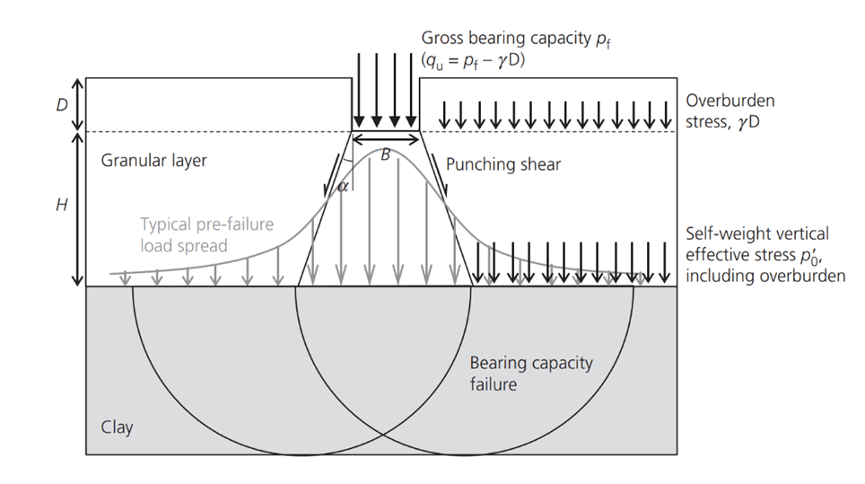
Figure 4 Geometry of the problem (Lees 2020)
A piling mat comprises a granular layer over a weaker subgrade soil, in this case, clay (Figure 4). The design must determine the required thickness of the granular layer to satisfy each load case. BR470 defines two critical loading conditions that must be examined for the specific piling rig being considered.
The T-value for non-stabilised granular material can be calculated or obtained from a chart (Figure 5). The three blue lines are T-value curves for different friction angles. A single T-value curve for a specific geogrid stabilised granular material is also shown on the chart in red. Different stabilisation geogrids will have similar but different T-value curves. Tensar has developed T-value curves for a range of their geogrids in a variety of granular materials.
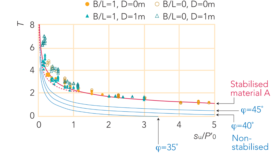
Figure 5 - T-Value variation with su undrained shear strength of clay for non-stabilised granular layers (blue) and a stabilised layer with a specific geogrid (red). (Lees & Matthias 2019)
Having determined the T-value, the two simple equations below in Figure 6 enable the calculation of the bearing capacity ratio for a strip footing (B/L = 0) and a square footing (B/L = 1), where B is the footing width, and B is the length.
Piling rigs have a rectangular footing where B is the track width, and L is the effective length of the track applying pressure. The effective track length L and pressure distribution are defined for each load case.
The bearing capacity ratio for a rectangular footing is obtained by linear extrapolation between the strip footing (B/L = 0) and square footing (B/L=1).
The inequalities in the two equations in Figure 3 are needed to check for cases where critical shear failure occurs entirely within the granular layer.
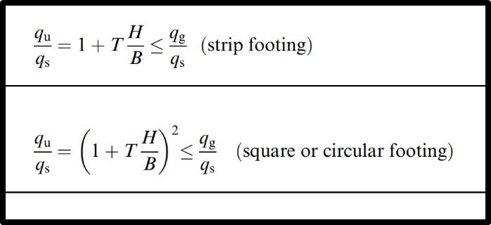
Figure 5 - Bearing capacity equations for strip and square/circular footings, where T represents the load transfer efficiency of the granular layer, qs=surface bearing capacity of subgrade when H=0, qg = surface bearing capacity of the granular layer when H=infinite. (Lees 2020)
Watch our video on how to use the T-value method to design a piling mat
Using Tensar+ free software for piling mat design
Tensar has incorporated the T-value method for the design of piling mats into Tensar+® software. This software is available free of charge from Tensar. It is easy for a competent geotechnical engineer to use.
Two design options are available: a Working Platform and a Tracked Plant. The second of these follows the requirements of BR470:2004 plus the guidelines of the BRE guidelines. This is the more appropriate option for piling mat design.

Figure 1 - Tensar+ offers two design options
Selecting the Tracked Plant option opens the design page. Load conditions can be input for each of the two load cases defined in BR470, together with the appropriate factors of safety for each. Next, the piling mat fill material properties can be entered. Finally, the subgrade characteristics and groundwater conditions are entered.
The design calculation is live. As data is input, required piling mat thicknesses for the stabilised and non-stabilised options are displayed graphically. For the stabilised case, the required geogrid type(s) and vertical spacing are displayed.
Value Calculation – A second tab opens a Value page. Typical material and geogrid costs are included by default, but these can be changed by entering project-specific materials costs. The designer can then identify the total costs for each option and the savings between stabilised and non-stabilised options. The costs and savings calculated and displayed are the construction cost and environmental cost, together with construction time.
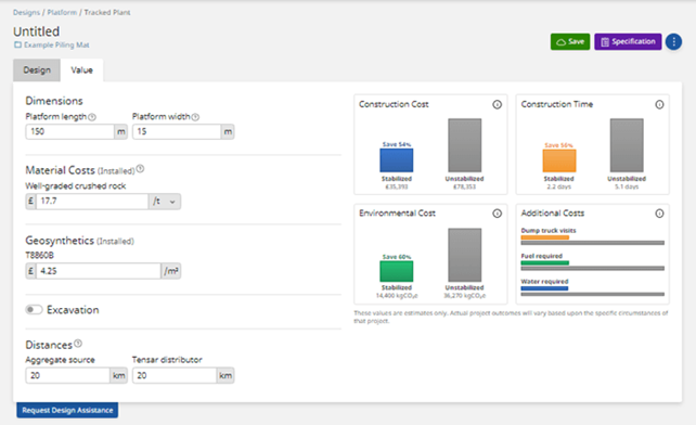
Figure 3 - Tensar+ Value calculation page
A further tab displays design-specific specification documents that can be incorporated into project documents.
Tensar+ software is cloud-based and may be accessed from PC’s or mobile devices. Completed designs can be stored and downloaded in PDF format for retention by the designer. Try out Tensar+ now.
Next steps
This guide has explained how to determine the piling mat specifications for your next construction project. By following the T-Value piling mat design process outlined above, you’ll be able to create a working platform that is stable enough to support your piling rigs without being overengineered for the task at hand.
See our T-Value guide for further information on applying this method to piling mat design. If you’re looking for extra support with your project, sign up for our free software, Tensar+ and navigate to the working platform design module.
Watch our new Tensar+ training video on our Tracked Plant module to understand more about how you can use this module to support your project.
References
- Lees, A.S. (2020) The bearing capacity of a granular layer on clay. Proceedings of the Institution of Civil engineers – Geotechnical Engineering, 173, No. 3, 448-452
- Lees, A. S. and Abid, A (2023) The surface bearing capacity of a strong granular layer on weaker sand. Proceedings of the Institution of Civil Engineers – Geotechnical Engineering, https://doi.org/10.1680/jgeen.22.00094
- Lees, A.S. and Clausen, J; (2019). The strength envelope of granular soil stabilised by multi-axial geogrid in large triaxial tests. Canadian Geotechnical Journalhttps://doi.org/10.1139/cgj-2019-0036
- Lees, A.S. and Matthias, P. (2019) Bearing capacity of a geogrid-stabilised granular layer on clay. Ground Engineering Nov.2019, 28-33